

Define safety requirements
This activity considers how the safety requirements are defined at each tier of decomposition in the system development process such that they adequately capture the intent of the safety requirements that were established at the previous tier of decomposition ([P]). This requires consideration of the design that is proposed for this tier of decomposition ([W]) such that safety requirements may be adequately decomposed and allocated to the relevant system components. The safety requirements must also be correctly interpreted for the allocated component to reflect the component design.
Example 24 - Different tiers of an autonomous system
We can identify the different tiers for a typical AS by considering the example in Figure 18 below, taken from [35], which shows a typical logical architecture for the controller of an autonomous vehicle. At the highest level, we could consider the AS itself as a tier of decomposition. At this level, the interactions between the AS and other entities would be considered. The next tier in Figure 18 would decompose this to the three main subsystems (Sensing, Control Block and Actuation) and their interactions. Each of these subsystems can then be seen to decompose at the next tier to components such as camera, LIDAR and GPS for the sensing subsystem, or Perception, Decision and Planning for the Control Block. Whereas the components may be considered the lowest level tier for the Sensing subsystem (since these are provided as developed units to the AS developer), further tiers of decomposition may be required for other components such as the Perception component, which is broken down to Localisation, Detection and Prediction. As illustrated in this example, the number of tiers required as part of the development process may not be uniform across all elements of an AS.
Note 14 - Intent of the safety requirements
In theory, all of the information required to demonstrate the adequacy of the decomposed safety requirements would be captured in the initial high‐level requirement. In practice, however, some of the information will always remain implicit. For AS, this could particularly be due to the complexity of the operating environment, but also to the fact that design decisions will always be made later in the development lifecycle that require greater detail in the requirements. This detail cannot be properly known until the design decisions have been made. For this reason, it is important to ensure that the intent of the safety requirements is maintained between levels of abstraction, with consideration being given to information that may not be fully specified in the requirement.
Figure 19, adapted from [21], illustrates how safety requirements are derived for a component of a single tier of decomposition in the development of an AS. This takes as input information from the previous tier of decomposition relating to the safety requirements placed on the components at this tier, as well as the design information. This information is used to create a design for the component (as discussed in Stage 5). This design will specify the sub‐components that are required and the relationships between those sub‐components.
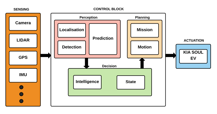
Figure 18: A simple example of the logical architecture for the controller of an autonomous vehicle (from [35])
Note 15 - Decomposing safety requirements
At the highest level of abstraction, which is the overall AS system level (“tier 0”) the safety requirements will be those defined by the SOC (see Stage 4). These will then be decomposed to more detailed safety requirements at the next tier of design decomposition (“tier 1”). Each time the safety requirements are further decomposed to more detailed tiers it is expected that additional safety requirements will be needed. Thus the total number of safety requirements specified for the AS will increase as more detail is added to the design of the system. It may also be the case when safety requirements are derived for a component, that additional safety requirements relevant to a previous tier are also identified. These safety requirements should be fed back up, in order to be correctly decomposed to the relevant system components.
Some of the sub‐components defined for a tier may be ready for implementation. For these components no further design activity is required; these components are at the stage where they can be implemented according to the requirements that are in place. These components are ready for verification and integration (see Stage 8). For other sub‐components further design may be required before they are ready for implementation. For these components a further tier of requirements decomposition will be required (along with further design activity). As shown in Figure 20, adapted from [21], different components may be ready to be integrated to the target AS platform at different tiers. Irrespective of the number of tiers in the development lifecycle of the system, the safety assurance considerations for the requirements at each tier remain the same: to derive safety requirements that adequately capture the intent of the the safety requirements specified at the previous tier, and to justify the sufficiency of those safety requirements.
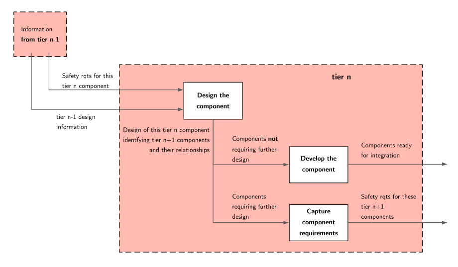
Figure 19: Defining safety requirements for components of a tier of design decomposition.
Note 16 - Link between safety requirements and the design process
The definition of safety requirements is intimately linked to the design process of the AS. It is important to note therefore that safety requirements may need to be re‐defined throughout the lifecycle based upon the architectural and design decisions that are taken. For example, many AS make extensive use of third‐party components to implement parts of the design (such as sensors). If a third‐party component is selected to be used, it may be found that the safety requirements that were originally derived for that component cannot be fully met by that third‐party component (the same could be true for legacy or re‐used components). This would therefore necessitate changes to the system design to mitigate those limitations (such as introducing additional components). This would then require a re‐definition of the safety requirements allocated to the components to reflect the changes to the design. It may then be possible to demonstrate that the third-party component can meet these redefined safety requirements.
Essentially it may be necessary to revisit the safety requirements at any tier multiple times as changes are made to the proposed design solution. What is crucial is that throughout this process, as changes are made to the design and the safety requirements, traceability is maintained to the safety requirements of the higher tier, and ultimately to the SOC for the AS operation.
Note 17 - Machine learning
Where safety requirements are allocated to a component that uses machine learning, the safety assurance of that component may be undertaken in accordance with the AMLAS guidance [20].